
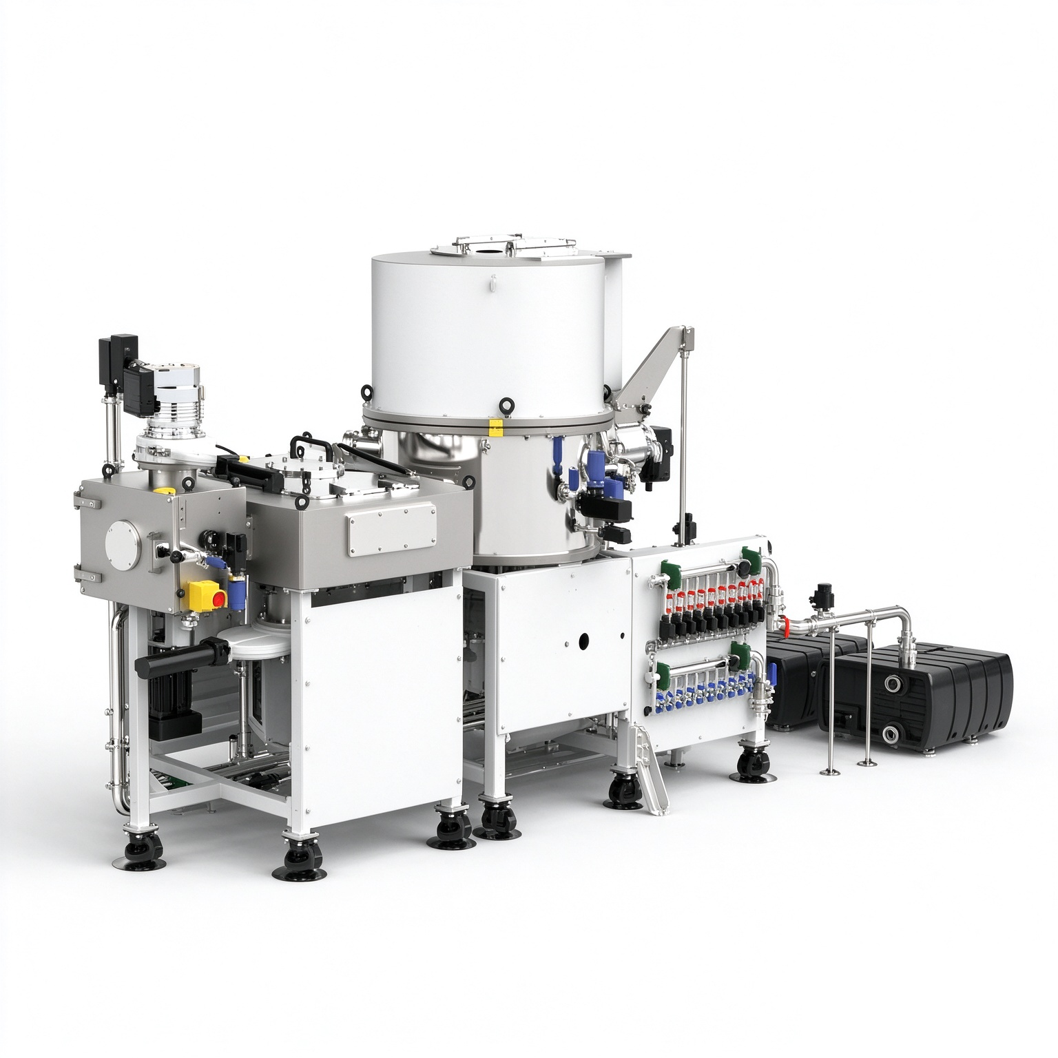
Equipment Description
This PVD magnetron sputtering system features a configuration comprising a load-lock chamber, a transfer module (TM) chamber, and a process chamber (3 chambers in total). It is equipped with four magnetron sputtering target positions designed for planar target sputtering on 2- to 8-inch wafers. It accommodates metal/alloy targets such as IGZO, ITO, and Al₂O₃ (using four 6-inch cathodes) with an adjustable target-to-substrate distance of 60–140 mm. Film thickness uniformity within a Φ200 mm area is ≤±3% (RMS, dual-target sputtering). Equipped with two sets each of DC and RF power supplies (0–600 W, ); the substrate stage features uniform heating (room temperature to 150°C) and supports substrate rotation at 1–30 rpm. Process gases (N₂, Ar, O₂, etc.) are controlled via MFC-based partial pressure regulation. The load-lock chamber evacuates from atmospheric pressure to 5 × 10⁻⁶ Torr within 60 minutes; the process chamber achieves a static vacuum of ≤1 × 10⁻⁸ Torr, with a leak rate below the 10⁻⁸ Torr•L/s level.
Technical Specifications
♦ Equipment Configuration: Load-lock chamber + Transfer Module (TM) chamber + Process chamber (configured with 4 magnetron sputtering targets)
♦ Primary Function: PVD planar target sputtering
♦ Chambers: Star Series (3 chambers total)
♦ Substrate Material & Size: Per customer requirements (wafer with trenches: width ~several microns, depth 100nm); 2–8 inch wafers
♦ Target Materials: IGZO, ITO, Al₂O₃, and other metals/alloys
♦ Target Specifications: ≥Φ150mm (thickness 5–10mm); 4 sets (6-inch cathodes)
♦ Target-to-Substrate Distance: Adjustable: 60–140mm (precision ±1mm)
♦ Coating Thickness: Per customer requirements
♦ Coating Uniformity: ≤±3% (RMS) over Φ200mm area (dual-target sputtering)
♦ Repeatability: Film thickness deviation ≤±3% over 10 consecutive runs (identical process parameters)
♦ Substrate Stage: Uniform heating (temperature variation ≤±1% across 200mm range); Rotation: 1–30 rpm; Heating: Room temperature to 150°C
♦ Real-time Monitoring: Real-time feedback of voltage, current, and power (graphical display available)
♦ Gas Lines: Process gases: N₂, Ar, O₂, etc.; Partial pressure control: Mass Flow Controllers (MFC) with accuracy ≤±1% S.P.
♦ Vacuum System: Independent pumping for load-lock chamber (turbomolecular pump + backing pump; pump-down time from atmosphere to 5×10⁻⁶ Torr ≤ 60 min); Independent pumping for process chamber (static base pressure ≤ 1×10⁻⁸ Torr); Leak rate: <10⁻⁸ Torr•L/s
♦ Cathode Power Supply: DC Power supply (0–600W), 2 sets; RF power supply (0–600 W), 2 sets